The post Video: How to Connect a PMDC Gearmotor to a Filtered PWM DC Speed Control appeared first on Bodine - Gearmotor Blog.
]]>
Copyright Bodine Electric Company © 10/2023. All rights reserved.
The post Video: How to Connect a PMDC Gearmotor to a Filtered PWM DC Speed Control appeared first on Bodine - Gearmotor Blog.
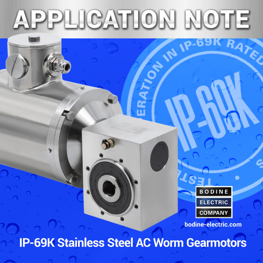
]]>The post What Does IP-69K Mean for Stainless Steel Gearmotors? appeared first on Bodine - Gearmotor Blog.
]]>Click here for the full article.
Copyright Bodine Electric Company © 10/2023. All rights reserved.
The post What Does IP-69K Mean for Stainless Steel Gearmotors? appeared first on Bodine - Gearmotor Blog.
]]>The post How To Connect a Reversing Switch to a 3- or 4-Wire (PSC) Gearmotor appeared first on Bodine - Gearmotor Blog.
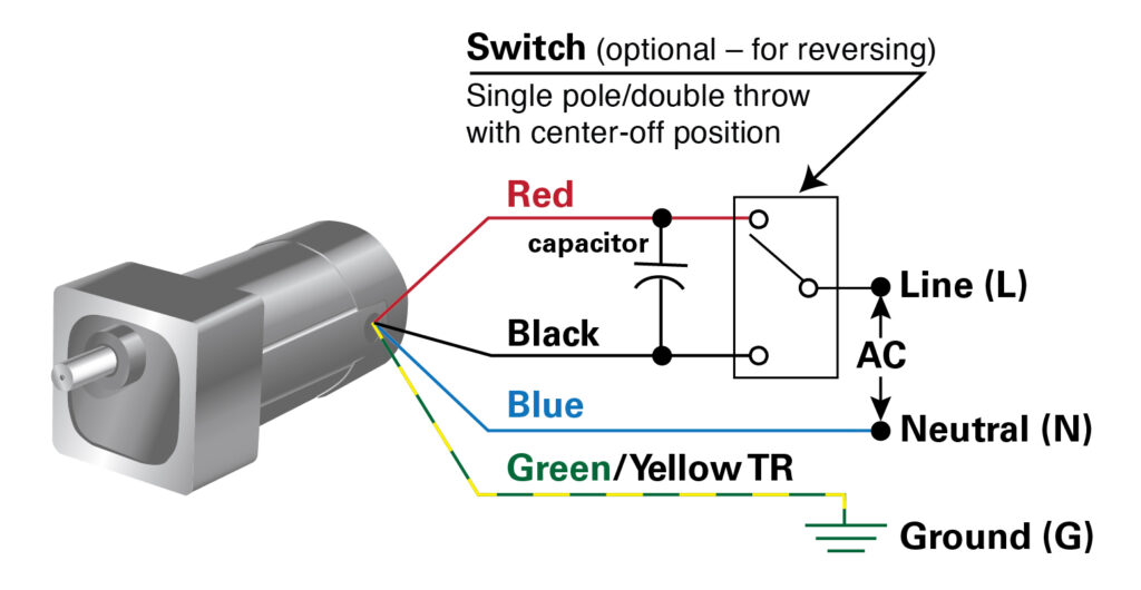
]]>How to Wire an Optional Reversing Switch to a 3- or 4-wire AC (PSC) Motor or Gearmotor (115VAC/60Hz Models)
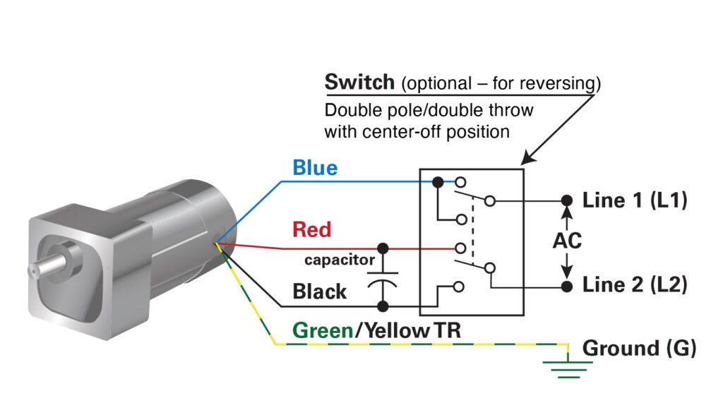
These connection diagrams show how to wire an optional switch to reverse the direction of a 3- or 4-wire Bodine permanent split capacitor (PSC) motor/gearmotor. All the wiring diagrams use variations of a double throw switch, with a center-off position. The purpose of the center-off position is to bring the gearmotor to a complete stop before reversing its direction of rotation. This is necessary to prevent gearing damage. Table 1 (below) shows examples of switch manufacturers, part numbers and specifications recommended for use with Bodine products.
——
To watch our How-To video on how to add a manual reversing switch to a Bodine 3-wire reversible PSC gearmotor or motor, click here. Our video for 4-wire reversible PSC motors is linked below.
3- Wire-Reversible Bodine AC Motor or Gearmotor
Examples 1 & 2 show how to connect a single- or double-pole switch to our 3-wire, PSC, fixed-speed AC gearmotors or motors.
4-Wire-Reversible Bodine AC Motor or Gearmotor
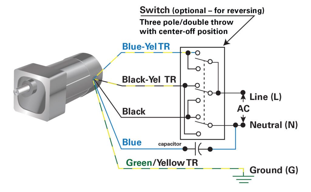
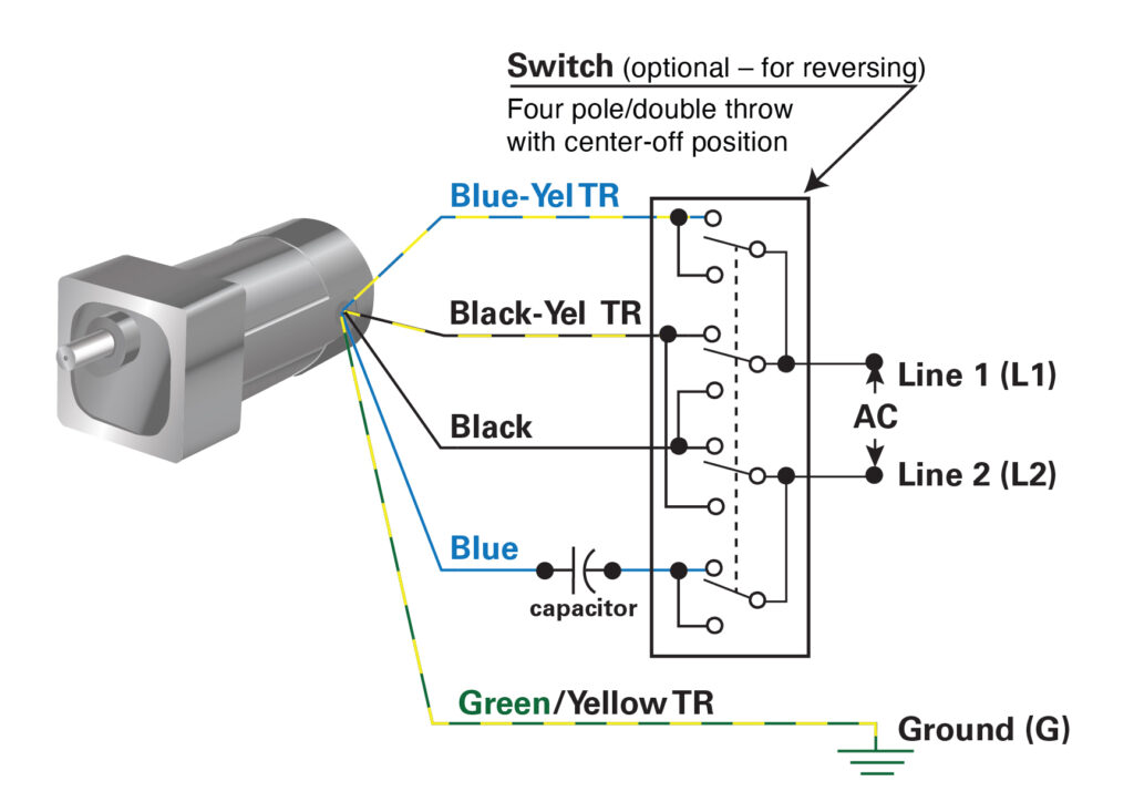
Examples 3 & 4 show how to connect a three- or four-pole switch to our 4-wire, PSC, fixed-speed AC gearmotors or motors.
| Table 1: Switch Specification Examples | |||||
|---|---|---|---|---|---|
| Figure | Switch Type | Manufacturer and Part Number | Amps | Operation | Terminals |
| Bodine 3-wire Gearmotor/Motor | |||||
| 1 | Single Pole, Double Throw | Carling Technologies, 2FC53-73-TABS | 15A @125VAC | On-Off-On | Quick Connect |
| 2 | Double Pole, Double Throw | Carling Technologies, 2GM51-73 | 15A @125VAC | On-Off-On | Quick Connect |
| Bodine 4-wire Gearmotor/Motor | |||||
| 3 | Three Pole, Double Throw | Carling Technologies, HM251-73 | 15A @125VAC | On- Off-On | Quick Connect |
| 4 | Four Pole, Double Throw | Carling Technologies, IM251-73 | 15A @125VAC | On- Off-On | Quick Connect |
Connection diagrams are available from our web site.
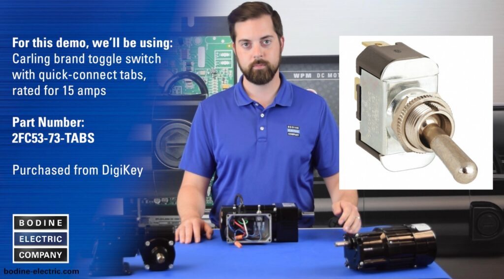
How-To Connect a Three-Pole, Double-Throw toggle switch to Reverse a 4-Wire Reversible 115VAC, PSC gearmotor or motor.
Several jumper wires are required to connect a reversing switch to one of our 4-wire-reversible, permanent split capacitor (PSC) gearmotors or motors. For our demo, we are using a Three-Pole, Double-Throw toggle switch with Center-Off position. (Carling brand switch with quick-connect tabs, rated for 15 Amps; Carling part number HM215-73 — purchased from DigiKey).
To watch our How-To Video for adding a reversing switch to a 4-wire, PSC gearmotor, click here.
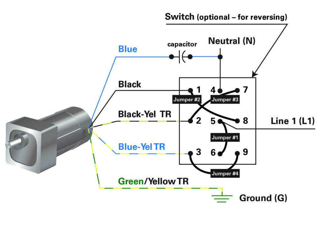
Connect the incoming power line (hot lead) and one side of a jumper lead and connect it to switch terminal 5, then connect the other end of jumper #1 with the switch terminal number 6, see diagram.
Connect the black motor lead with one side of a jumper lead and land on switch terminal 1, connect the other side of jumper #2 with switch terminal 8, see diagram.
Connect the black/yellow tracer motor lead with one side of jumper #3 lead, and connect it to switch terminal 2, then connect the other side of jumper#3 to switch terminal 7.
For the last jumper, connect the blue/yellow tracer lead with one side of our jumper #4 lead, and then connect it to terminal 3 of the switch, then connect the other side of jumper #4 to terminal 9 of the reversing switch.
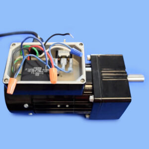
The blue motor lead is wired to one side of the capacitor (non-polarized) and the other side of the capacitor is crimped together with the neutral line, and then connected to switch terminal number 4.
Copyright Bodine Electric Company © 01/2023. All rights reserved.
The post How To Connect a Reversing Switch to a 3- or 4-Wire (PSC) Gearmotor appeared first on Bodine - Gearmotor Blog.
]]>The post Bodine Launches Competitor Cross-Reference Tool for Baldor, Bison, or Leeson Gearmotor Replacements appeared first on Bodine - Gearmotor Blog.
]]>Each competitor part number is constructed differently:
For example, if you are crossing a Baldor item, the part number will look something like this GCP24004, please do not add any additional spaces, dashes, or any type of alphanumeric characters to the search box as this will not bring up the correct information.
Bison part number, e.g. 011-190-0271, please enter the P/N with dashes just like this and the results will appear for you.
Leeson part number, e.g. M1145039.00, please enter it like this, do not include any spaces, dashes, or additional alphanumeric information.

When you perform a cross-reference search for a Baldor, Bison or Leeson stock product, here are the possible search results: (a) Bodine drop-in, (b) we offer an “almost” drop in, with differences explained; (c) no drop in, no Bodine alternative, call our CS team, (d) no search result, not in our database, please call us.
If we do not offer a “drop-in”, but the item is in our competitor database, then we explain the differences so you can compare the specs with our closest stock model. If no cross-reference is available, please reach out to us directly and call us at: 773-478-3515 (USA) and ask for an application engineer, or send your email request to: info@bodine-electric.com.
Copyright Bodine Electric Company © 10/2022. All rights reserved.
The post Bodine Launches Competitor Cross-Reference Tool for Baldor, Bison, or Leeson Gearmotor Replacements appeared first on Bodine - Gearmotor Blog.
]]>The post How to Connect a Run Capacitor to a AC 4-Wire-Reversible PSC Gearmotor or Motor appeared first on Bodine - Gearmotor Blog.
]]>For more application notes and wiring info, visit: https://www.bodine-electric.com/application-notes
Copyright Bodine Electric Company © 08/2022. All rights reserved.
The post How to Connect a Run Capacitor to a AC 4-Wire-Reversible PSC Gearmotor or Motor appeared first on Bodine - Gearmotor Blog.
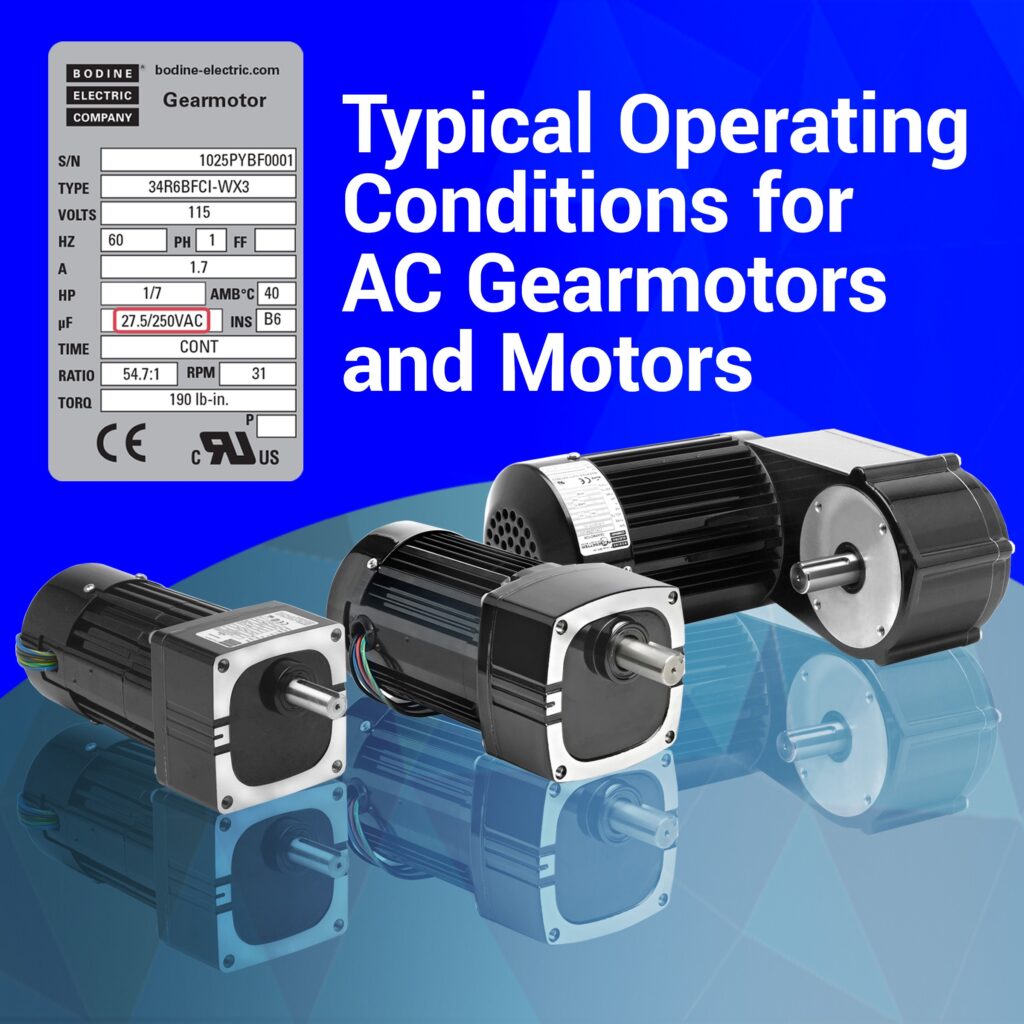
]]>The post Typical Operating Conditions for AC Gearmotors and Motors appeared first on Bodine - Gearmotor Blog.
]]>With this new Tech Note from our engineering team, you’ll learn how operating a gearmotor or motor above or below the ratings shown on its product nameplate can affect performance. For standard gearmotors, the torque rating shown on the product nameplate (or in the manufacturer’s sales literature) represents a complete gearmotor rating and reflects the capacity of the limiting gearmotor design elements. Some of the design limitations considered are: motor input power, strength or wear rating of the gearing. Click here for the full article.
Copyright Bodine Electric Company © 06/2022. All rights reserved.
The post Typical Operating Conditions for AC Gearmotors and Motors appeared first on Bodine - Gearmotor Blog.
]]>The post New Video: How to Connect a Reversing Switch to a 3-Wire-Reversible PSC Gearmotor appeared first on Bodine - Gearmotor Blog.
]]>
Or visit: https://youtu.be/NZTpbi_M2io
Copyright Bodine Electric Company © 02/2022. All rights reserved.
The post New Video: How to Connect a Reversing Switch to a 3-Wire-Reversible PSC Gearmotor appeared first on Bodine - Gearmotor Blog.
]]>The post Introduction to Motor Constants for Fractional Horsepower Gearmotors appeared first on Bodine - Gearmotor Blog.
]]>
Common Motor Constants:
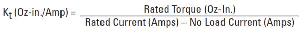
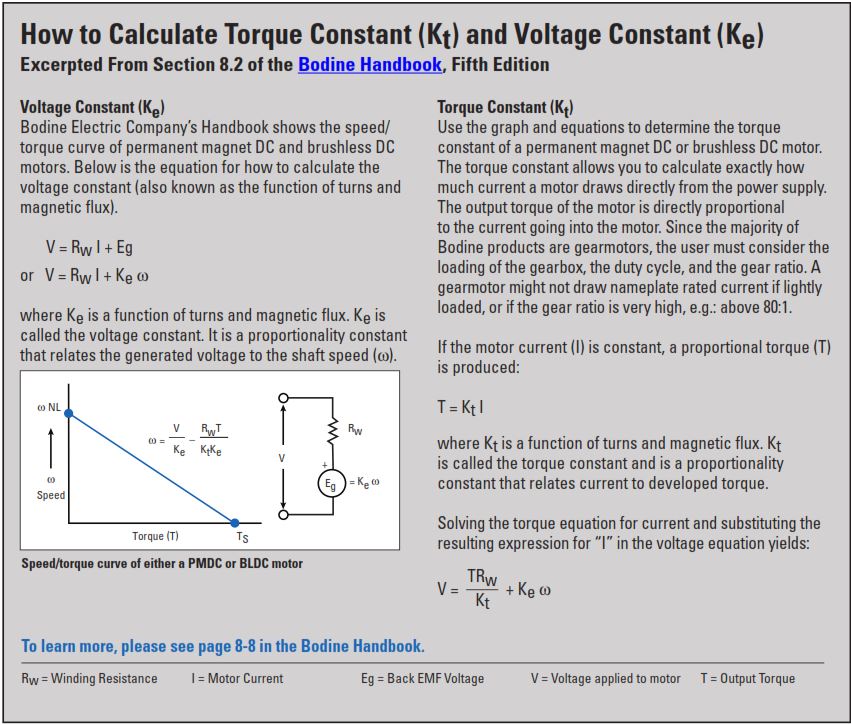
The most commonly used motor constants are Torque Constant (Kt), Voltage Constant (Ke), Electrical Time Constant (Te), Mechanical Time Constant (Tm), and Thermal Resistance (Rth). Typical values for these constants are derived by using measured values of No Load Speed, No Load Current, Stall Torque, Circuit Resistance, Circuit Inductance, and Armature Inertia with the following equations:
Torque Constant (Kt) — describes the proportional relationship between torque and current. Kt is usually expressed in the units Oz-in./Amp. See page 2 for additional information about torque constants.
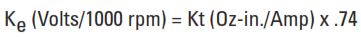
Voltage Constant, or Back EMF Constant (Ke) — is the Torque Constant expressed in different units, usually Volts/Krpm, in order to describe the proportional relationship between motor speed and generated output voltage when the motor is back driven as a generator in units of Volts/1000 rpm. See page 2 for additional information about voltage constants.
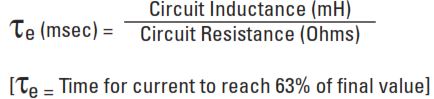
Electrical Time Constant (Te) — is the time required for a motor to reach 63.2% of its stall current after applying a test voltage with the motor shaft locked. It is usually expressed in milliseconds. Applied Voltage equals Rated Current multiplied by Circuit Resistance:
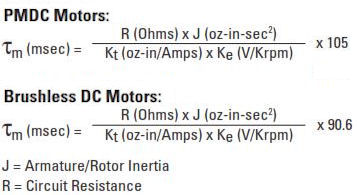
Mechanical Time Constant (Tm) — is the time required for an unloaded motor to reach 63.2% of its no load speed after applying its rated voltage. It is usually expressed in milliseconds.
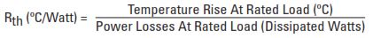
Thermal Resistance (Rth) — is useful for predicting the ultimate temperature rise under different loading conditions in order to determine a maximum continuous torque rating. It is usually expressed in the units °C/Watt.
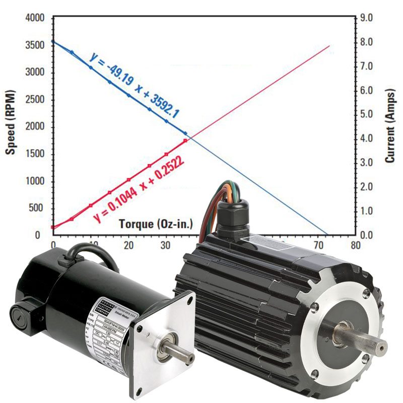
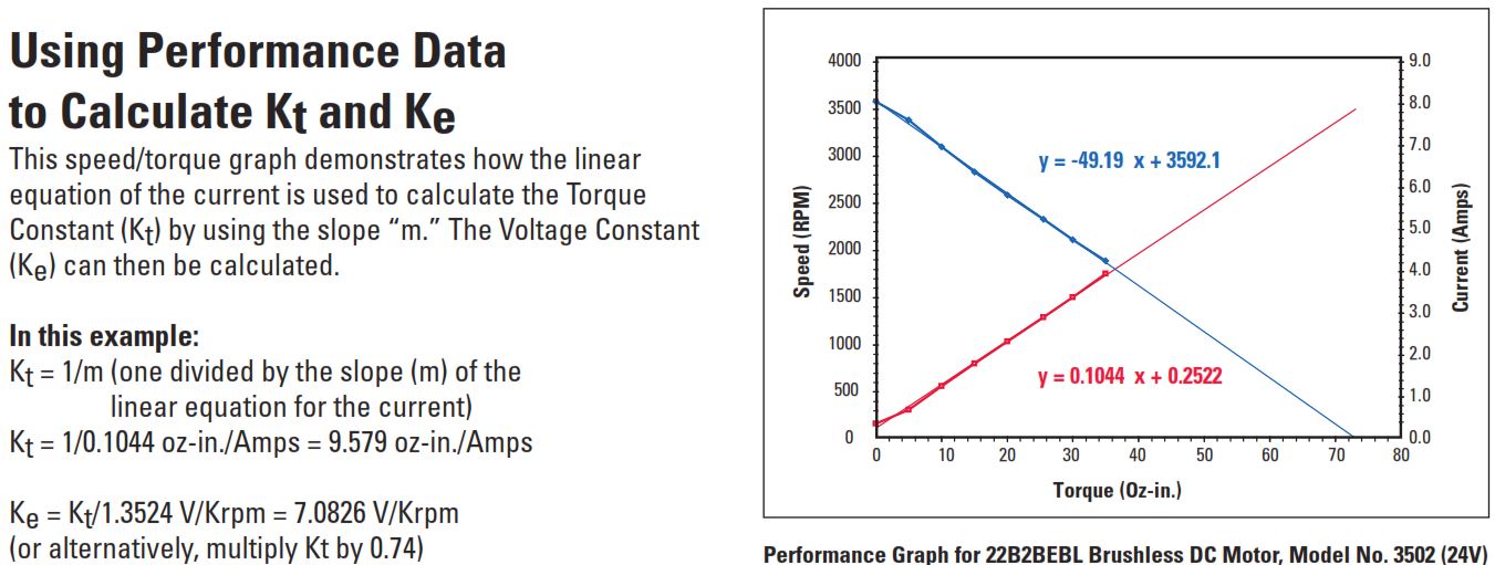
Using Performance Data to Calculate Kt and Ke
This speed/torque graph demonstrates how the linear equation of the current is used to calculate the Torque Constant (Kt) by using the slope “m.” The Voltage Constant (Ke) can then be calculated.
Using Performance Data to Calculate Kt and Ke
This speed/torque graph demonstrates how the linear equation of the current is used to calculate the Torque Constant (Kt) by using the slope “m.” The Voltage Constant (Ke) can then be calculated.
To download this information as a PDF, click here.
To download the Motor Constants for Standard Bodine Gearmotors, click here.
To download Chapter 8, or any other section of the Bodine Small Motors Handbook, click here.
Bonus Tech Tip: Another handy use for motor constants is when performing load measurements. If you are designing a machine and want to use an AC gearmotor, but you don’t know what size gearmotor you need. AC motors don’t have torque constants, but DC motors do. You might install a DC gearmotor into your prototype machine and use it as a “torque transducer”. By measuring the current draw, you can estimate what torque is needed when you start shopping for the AC gearmotor on Bodine Electric Company’s website
Copyright Bodine Electric Company © 11/2021. All rights reserved.
The post Introduction to Motor Constants for Fractional Horsepower Gearmotors appeared first on Bodine - Gearmotor Blog.
]]>The post Custom Gearmotors Solve AGV / AMR Challenge appeared first on Bodine - Gearmotor Blog.
]]> Large distribution warehouses operated by wholesalers, retailers, or large manufacturers have turned to Automated Guided Vehicles (AGVs) or Autonomous Mobile Robots (AMRs) to keep up with ever-increasing demand for faster and more economical deliveries. A major original equipment manufacturer (OEM) for AGVs contacted Bodine Electric Company to help develop two new custom gearmotors for their latest AGV. Bodine has since built, tested and shipped over 50,000 gearmotors to this customer.
The Challenge 
The OEM’s specifications required two gearmotors, one of them had to lift up to 1,000 lbs (with substantial peak loads). The AGV’s chassis had already been finalized, and left only limited space for the new gearmotors. The gearmotors were required to operate almost continuously for five years, under worst-case environmental conditions, and would be subjected to extreme vibration and shock.
The Result
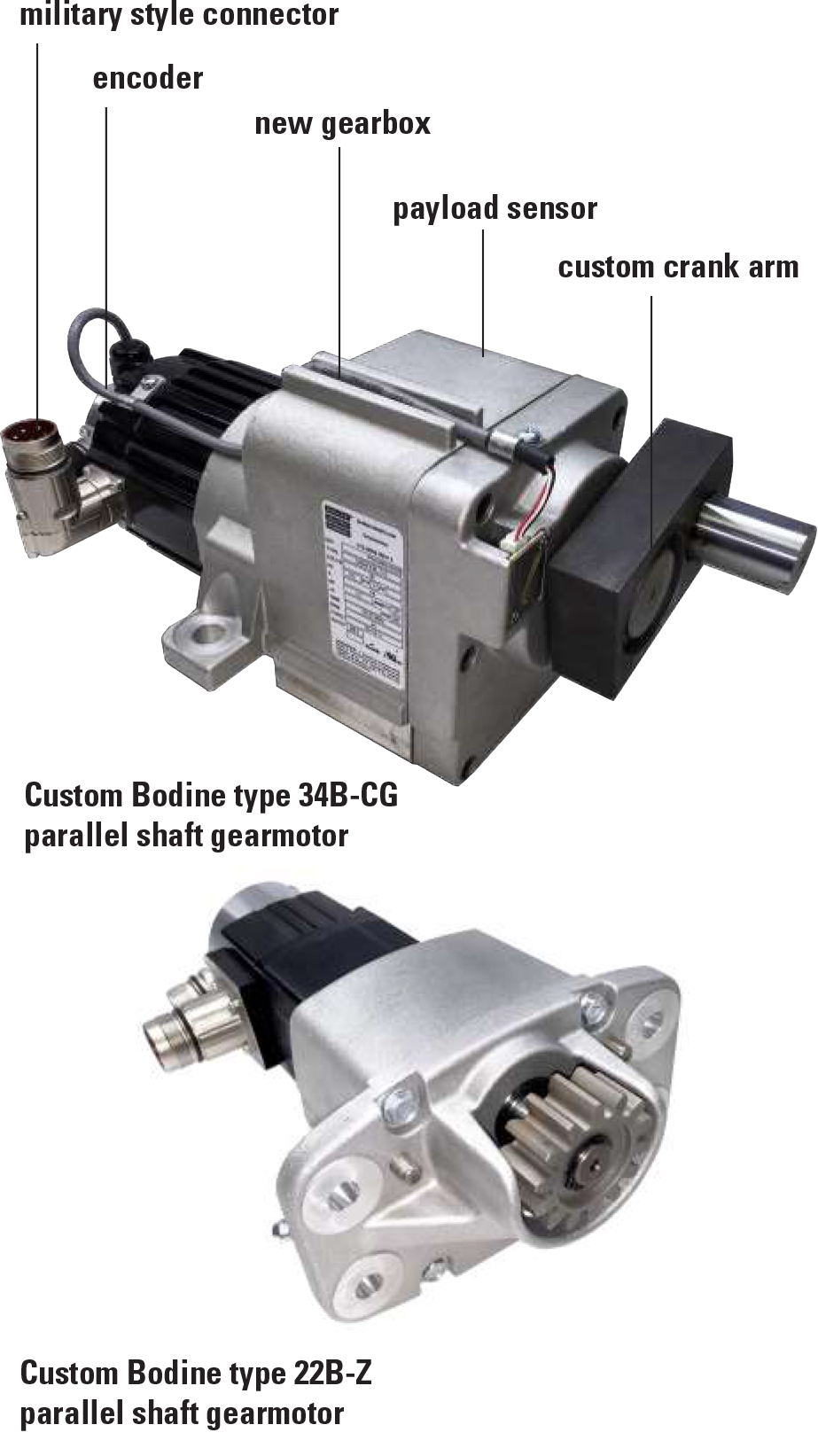
Almost every part of these new gearmotors was engineered to match the customer’s extensive list of requirements.
- Low-voltage brushless DC motors paired with all-new, highly efficient gearboxes prolong the AGV battery life and minimize downtime
- Gearbox designed to simplify the assembly process of the AGV
- Custom output shaft assembly designed for extremely heavy loads
- Feedback device tracked the position of the drive shaft
- 1024 PPR encoder provided servo feedback to control the gearmotors
- “Military Style” plug and screw connections
- Temperature sensors monitor gearmotor performance and to prevent overloads
- Manual over-ride in the event of a power failure
 With Bodine’s help, these sophisticated robotic vehicles have been performing flawlessly all over the world. Bodine not only developed two entirely new gearmotors for the application, they also helped navigate the difficult third-party approval process. Bodine engineers extensive experience in motion control made them an ideal partner in the development of this new product, which in turn is making warehouse jobs easier, more productive, and cost-efficient.
Bodine Electric engineers bring over 115 years of application engineering and problem solving experience to a wide range of applications in industries as diverse as medical, packaging, industrial automation, and solar powered outdoors equipment. We look forward to working with you on your next FHP gearmotor design challenge.
To download this article as a PDF, click here
Copyright Bodine Electric Company © 10/2021.
All rights reserved.
The post Custom Gearmotors Solve AGV / AMR Challenge appeared first on Bodine - Gearmotor Blog.
]]>The post Gearmotors for Commercial Food Equipment appeared first on Bodine - Gearmotor Blog.
]]>https://www.bodine-electric.com/industries/food-equipment
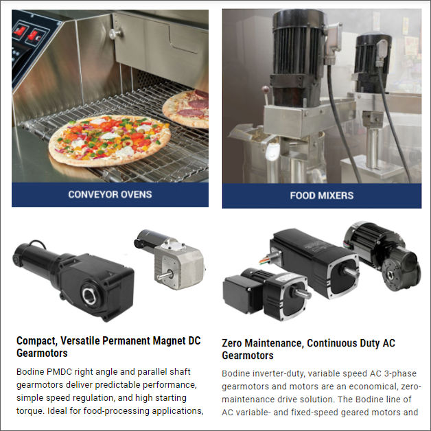
#fractionalHorsepower #gearmotor #FoodEquipment #FoodProcess #cookingEquipment #conveyorOven #pizzaOvens #foodMixers #mixers #capping #baggers #AC #inverterDuty #variableSpeed #BLDC #PMDC #gearmotors
Copyright Bodine Electric Company © 07/2021. All rights reserved.
The post Gearmotors for Commercial Food Equipment appeared first on Bodine - Gearmotor Blog.
]]>