The post Bodine Electric Type WX Gearmotors Now Have Higher Torque Ratings appeared first on Bodine - Gearmotor Blog.
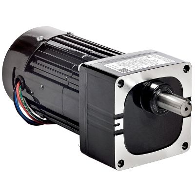
]]>Bodine Electric Company recently upgraded the design of many of our type WX gearmotors to increase the output torque ratings while maintaining the same long-life rating. Two parts in the gearhead design were changed to accomplish the higher torque ratings: the rotor/armature shaft and the first stage gear. The rotor is the name for the rotating part in an AC Induction motor or a Brushless DC motor. The armature is the name for the rotating part in a Brushed DC motor. Regardless of what it’s called, that rotating part, when in a parallel shaft gearmotor like Bodine’s type WX gearmotor, has a shaft with a pinion cut on the end that engages with the first stage gear in the gearhead.
Achieving smooth and continuous torque requires careful consideration of the design and manufacturing techniques, gear materials, and heat treatment processes. Since the rotor/armature shaft pinion is subjected to significantly more load cycles than the mating first stage gear, it is common practice to design the pinion with a higher hardness than the gear. For the type WX gearmotors, Bodine Electric engineers raised the bar by choosing a pinion steel alloy with higher hardenability and a gear steel alloy with higher fatigue strength.
This design change allowed Bodine to raise the output torque rating for any WX gear ratio where the first stage of the gearing cluster had been the “weak link”. This included all of the two-stage ratios used in Bodine stock models (3.8:1, 5.5:1, 9.4:1, 13.8:1, and 20.4:1) and two of the three-stage ratios used in Bodine stock models (29.7:1 and 43.9:1).
The following tables show the specific torque rating changes for each stock model number that was affected.
Bodine Electric types 34R4BFPP-WX2 and 34R4BFPP-WX3 are powered by Three Phase AC, either direct from the line or from an adjustable frequency drive (inverter). The only models shown in the table below are those that had a change in nameplate ratings.
| Model No. | Gear Ratio (:1) | Old Torque Rating (lb-in) | New Torque Rating (lb-in) | Change |
|---|---|---|---|---|
| 2808 | 43.9 | 157 | 185 | +18% |
| 2809 | 29.7 | 106 | 150 | +42% |
| 2829 | 20.4 | 77 | 109 | +42% |
| 2830 | 13.8 | 46 | 70 | +52% |
| 2831 | 9.4 | 31 | 45 | +45% |
| 2832 | 5.5 | 18 | 26 | +44% |
| 2833 | 3.8 | 9 | 18 | +100% |
AC Single Phase Models

Bodine Electric types 34R6BFCI-WX2 and 34R6BFCI-WX3 are powered by single phase 115 VAC and require a capacitor for operation. The only models shown in the table below are those that had a change in nameplate ratings.
| Model No. | Gear Ratio (:1) | Old Torque Rating (lb-in) | New Torque Rating (lb-in) | Change |
|---|---|---|---|---|
| 1023 | 43.9 | 157 | 185 | +18% |
| 1021 | 29.7 | 106 | 128 | +21% |
| 1019 | 20.4 | 77 | 93 | +21% |
| 1016 | 13.8 | 46 | 59 | +28% |
| 1014 | 9.4 | 31 | 38 | +23% |
| 1012 | 5.5 | 18 | 22 | +22% |
| 1010 | 3.8 | 9 | 15 | +67% |
Brushed DC 24 Volt Models (also rated for 12 Volts)

Bodine Electric types 33A5BEPM-WX2, 33A5FEPM-WX2, 33A5BEPM-WX3, and 33A5FEPM-WX3 are powered by a low voltage DC supply, often a battery. The 24 VDC models can also be operated from 12 VDC, but at a much lower speed. They are offered both with and without a high speed accessory shaft for mounting a brake or encoder. The only models shown in the table below are those that had a change in nameplate ratings.
| Model No. (with & w/o accessory shaft) | Gear Ratio (:1) | Old Torque Rating (lb-in) | New Torque Rating (lb-in) | Change |
|---|---|---|---|---|
| 1412 / 1212 | 43.9 | 157 | 181 | +15% |
| 1410 / 1210 | 29.7 | 106 | 151 | +42% |
| 1408 / 1208 | 20.4 | 77 | 110 | +43% |
| 1406 / 1206 | 13.8 | 46 | 70 | +52% |
| 1404 / 1204 | 9.4 | 31 | 45 | +45% |
| 1402 / 1202 | 5.5 | 18 | 26 | +44% |
| 1400 / 1200 | 3.8 | 9 | 18 | +100% |
Brushed DC 130 Volt Models (also rated for 90 Volts)
Bodine Electric types 33A5BEPM-WX2, 33A5FEPM-WX2, 33A5BEPM-WX3, and 33A5FEPM-WX3 are powered by a 130 VDC supply, usually coming from a 115 VAC powered speed control. The 130 VDC models can also be operated from 90 VDC, but at a lower speed and torque (if the speed control has an unfiltered DC output). They are offered both with and without a high-speed accessory shaft for mounting a brake or encoder. The only models shown in the table below are those that had a change in nameplate ratings.
| Model No. (with & w/o accessory shaft) | Gear Ratio (:1) | Old Torque Rating (lb-in) | New Torque Rating (lb-in) | Change |
|---|---|---|---|---|
| 1442 / 1062 | 43.9 | 157 | 181 | +15% |
| 1440 / 1060 | 29.7 | 106 | 144 | +36% |
| 1438 / 1058 | 20.4 | 77 | 104 | +35% |
| 1436 / 1056 | 13.8 | 46 | 67 | +46% |
| 1434 / 1054 | 9.4 | 31 | 43 | +39% |
| 1432 / 1052 | 5.5 | 18 | 25 | +39% |
| 1430 / 1050 | 3.8 | 9 | 17 | +89% |
Brushed DC 90 Volt Models & 180 Volt Models
Bodine Electric types 33A5BEPM-WX2 and 33A5BEPM-WX3 are powered by either a 90 VDC supply or a 180 VDC supply, depending on the model number. In either case, the DC supply usually comes from an AC-powered speed control (with the AC power being either 115 VAC or 230 VAC). The only models shown in the table below are those that had a change in nameplate ratings.
| Model No. (90 Volt & 180 Volt) | Gear Ratio (:1) | Old Torque Rating (lb-in) | New Torque Rating (lb-in) | Change |
|---|---|---|---|---|
| 1251 / 1154 | 13.8 | 39 | 41 | +5% |
| 1248 / 1150 | 3.8 | 9 | 11 | +22% |
Brushless DC 24 Volt Models

Bodine Electric types 34B3BEBL-WX2, 34B3FEBL-WX2, 34B3BEBL-WX3, and 34B3FEBL-WX3 are used with an electronic control for brushless commutation that is powered by a 24 VDC supply, often a battery. They are offered both with and without a high-speed accessory shaft for mounting a brake or encoder. The only models shown in the table below are those that had a change in nameplate ratings.
| Model No. (with & w/o accessory shaft) | Gear Ratio (:1) | Old Torque Rating (lb-in) | New Torque Rating (lb-in) | Change |
|---|---|---|---|---|
| 1316 / 1286 | 43.9 | 157 | 180 | +15% |
| 1315 / 1285 | 29.7 | 106 | 121 | +14% |
| 1314 / 1284 | 20.4 | 77 | 88 | +14% |
| 1313 / 1283 | 13.8 | 46 | 56 | +22% |
| 1312 / 1282 | 9.4 | 31 | 36 | +16% |
| 1310 / 1280 | 5.5 | 18 | 21 | +17% |
| 1309 / 1279 | 3.8 | 9 | 15 | +67% |
Brushless DC 130 Volt Models
Bodine Electric types 34B3BEBL-WX2, 34B3FEBL-WX2, 34B3BEBL-WX3, and 34B3FEBL-WX3 are used with an electronic control for brushless commutation that is usually powered from a 115 VAC line. They are offered both with and without a high-speed accessory shaft for mounting a brake or encoder. The only models shown in the table below are those that had a change in nameplate ratings.
| Model No. (with & w/o accessory shaft) | Gear Ratio (:1) | Old Torque Rating (lb-in) | New Torque Rating (lb-in) | Change |
|---|---|---|---|---|
| 1116 / 1086 | 43.9 | 157 | 180 | +15% |
| 1115 / 1085 | 29.7 | 106 | 121 | +14% |
| 1114 / 1084 | 20.4 | 77 | 88 | +14% |
| 1113 / 1083 | 13.8 | 46 | 56 | +22% |
| 1112 / 1082 | 9.4 | 31 | 36 | +16% |
| 1110 / 1080 | 5.5 | 18 | 21 | +17% |
| 1109 / 1079 | 3.8 | 9 | 15 | +67% |
Brushless DC 12 Volt Models with Integral Control
Bodine Electric types 34B4BEBL/SR-WX2 and 34B4BEBL/SR-WX3 have integral electronic controls for brushless commutation and for speed control that are powered by a 12 VDC power supply, often a battery. The only models shown in the table below are those that had a change in nameplate ratings.
| Model No. | Gear Ratio (:1) | Old Torque Rating (lb-in) | New Torque Rating (lb-in) | Change |
|---|---|---|---|---|
| 3286 | 43.9 | 157 | 180 | +15% |
| 3285 | 29.7 | 106 | 121 | +14% |
| 3284 | 20.4 | 77 | 88 | +14% |
| 3283 | 13.8 | 46 | 56 | +22% |
| 3282 | 9.4 | 31 | 36 | +16% |
| 3280 | 5.5 | 18 | 21 | +17% |
| 3279 | 3.8 | 9 | 15 | +67% |
Brushless DC 24 Volt Models with Integral Control
Bodine Electric types 34B4BEBL/SR-WX2 and 34B4BEBL/SR-WX3 have integral electronic controls for brushless commutation and for speed control that are powered by a 24 VDC power supply, often a battery. The only models shown in the table below are those that had a change in nameplate ratings.
| Model No. | Gear Ratio (:1) | Old Torque Rating (lb-in) | New Torque Rating (lb-in) | Change |
|---|---|---|---|---|
| 3886 | 43.9 | 157 | 181 | +15% |
| 3885 | 29.7 | 106 | 153 | +44% |
| 3884 | 20.4 | 77 | 111 | +44% |
| 3883 | 13.8 | 46 | 71 | +54% |
| 3882 | 9.4 | 31 | 46 | +48% |
| 3880 | 5.5 | 18 | 27 | +50% |
| 3879 | 3.8 | 9 | 18 | +100% |
The post Bodine Electric Type WX Gearmotors Now Have Higher Torque Ratings appeared first on Bodine - Gearmotor Blog.
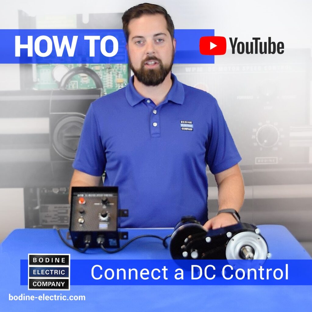
]]>The post Video: How to Connect a PMDC Gearmotor to a Filtered PWM DC Speed Control appeared first on Bodine - Gearmotor Blog.
]]>
Copyright Bodine Electric Company © 10/2023. All rights reserved.
The post Video: How to Connect a PMDC Gearmotor to a Filtered PWM DC Speed Control appeared first on Bodine - Gearmotor Blog.
]]>The post How To Connect a Reversing Switch to a 3- or 4-Wire (PSC) Gearmotor appeared first on Bodine - Gearmotor Blog.
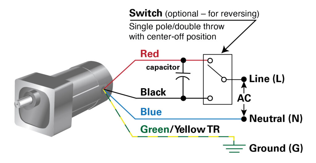
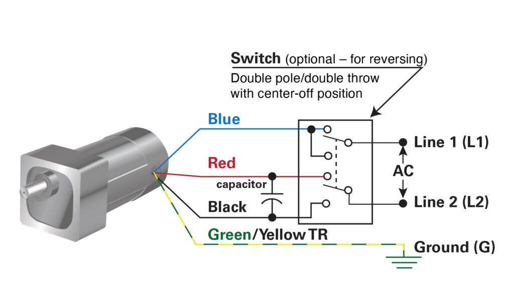
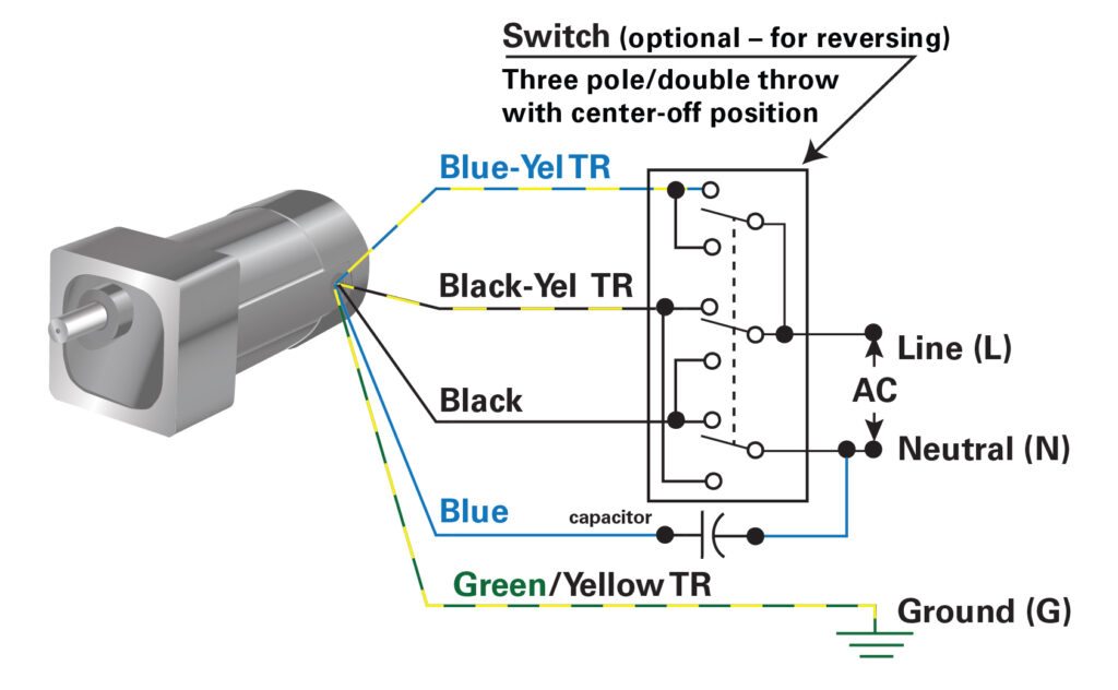
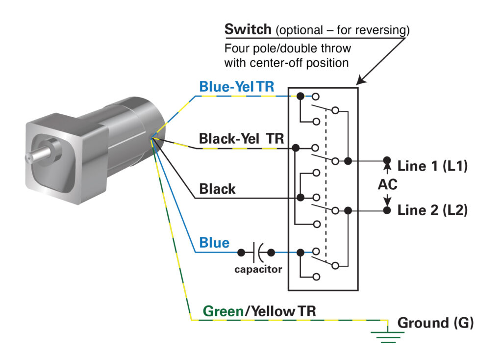
]]>How to Wire an Optional Reversing Switch to a 3- or 4-wire AC (PSC) Motor or Gearmotor (115VAC/60Hz Models)
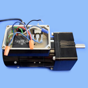
These connection diagrams show how to wire an optional switch to reverse the direction of a 3- or 4-wire Bodine permanent split capacitor (PSC) motor/gearmotor. All the wiring diagrams use variations of a double throw switch, with a center-off position. The purpose of the center-off position is to bring the gearmotor to a complete stop before reversing its direction of rotation. This is necessary to prevent gearing damage. Table 1 (below) shows examples of switch manufacturers, part numbers and specifications recommended for use with Bodine products.
——
To watch our How-To video on how to add a manual reversing switch to a Bodine 3-wire reversible PSC gearmotor or motor, click here. Our video for 4-wire reversible PSC motors is linked below.
3- Wire-Reversible Bodine AC Motor or Gearmotor
Examples 1 & 2 show how to connect a single- or double-pole switch to our 3-wire, PSC, fixed-speed AC gearmotors or motors.
4-Wire-Reversible Bodine AC Motor or Gearmotor
Examples 3 & 4 show how to connect a three- or four-pole switch to our 4-wire, PSC, fixed-speed AC gearmotors or motors.
| Table 1: Switch Specification Examples | |||||
|---|---|---|---|---|---|
| Figure | Switch Type | Manufacturer and Part Number | Amps | Operation | Terminals |
| Bodine 3-wire Gearmotor/Motor | |||||
| 1 | Single Pole, Double Throw | Carling Technologies, 2FC53-73-TABS | 15A @125VAC | On-Off-On | Quick Connect |
| 2 | Double Pole, Double Throw | Carling Technologies, 2GM51-73 | 15A @125VAC | On-Off-On | Quick Connect |
| Bodine 4-wire Gearmotor/Motor | |||||
| 3 | Three Pole, Double Throw | Carling Technologies, HM251-73 | 15A @125VAC | On- Off-On | Quick Connect |
| 4 | Four Pole, Double Throw | Carling Technologies, IM251-73 | 15A @125VAC | On- Off-On | Quick Connect |
Connection diagrams are available from our web site.
How-To Connect a Three-Pole, Double-Throw toggle switch to Reverse a 4-Wire Reversible 115VAC, PSC gearmotor or motor.
Several jumper wires are required to connect a reversing switch to one of our 4-wire-reversible, permanent split capacitor (PSC) gearmotors or motors. For our demo, we are using a Three-Pole, Double-Throw toggle switch with Center-Off position. (Carling brand switch with quick-connect tabs, rated for 15 Amps; Carling part number HM215-73 — purchased from DigiKey).
To watch our How-To Video for adding a reversing switch to a 4-wire, PSC gearmotor, click here.
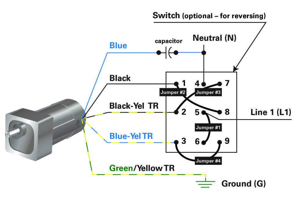
Connect the incoming power line (hot lead) and one side of a jumper lead and connect it to switch terminal 5, then connect the other end of jumper #1 with the switch terminal number 6, see diagram.
Connect the black motor lead with one side of a jumper lead and land on switch terminal 1, connect the other side of jumper #2 with switch terminal 8, see diagram.
Connect the black/yellow tracer motor lead with one side of jumper #3 lead, and connect it to switch terminal 2, then connect the other side of jumper#3 to switch terminal 7.
For the last jumper, connect the blue/yellow tracer lead with one side of our jumper #4 lead, and then connect it to terminal 3 of the switch, then connect the other side of jumper #4 to terminal 9 of the reversing switch.
The blue motor lead is wired to one side of the capacitor (non-polarized) and the other side of the capacitor is crimped together with the neutral line, and then connected to switch terminal number 4.
Copyright Bodine Electric Company © 01/2023. All rights reserved.
The post How To Connect a Reversing Switch to a 3- or 4-Wire (PSC) Gearmotor appeared first on Bodine - Gearmotor Blog.
]]>The post Bodine Launches Competitor Cross-Reference Tool for Baldor, Bison, or Leeson Gearmotor Replacements appeared first on Bodine - Gearmotor Blog.
]]>Each competitor part number is constructed differently:
For example, if you are crossing a Baldor item, the part number will look something like this GCP24004, please do not add any additional spaces, dashes, or any type of alphanumeric characters to the search box as this will not bring up the correct information.
Bison part number, e.g. 011-190-0271, please enter the P/N with dashes just like this and the results will appear for you.
Leeson part number, e.g. M1145039.00, please enter it like this, do not include any spaces, dashes, or additional alphanumeric information.

When you perform a cross-reference search for a Baldor, Bison or Leeson stock product, here are the possible search results: (a) Bodine drop-in, (b) we offer an “almost” drop in, with differences explained; (c) no drop in, no Bodine alternative, call our CS team, (d) no search result, not in our database, please call us.
If we do not offer a “drop-in”, but the item is in our competitor database, then we explain the differences so you can compare the specs with our closest stock model. If no cross-reference is available, please reach out to us directly and call us at: 773-478-3515 (USA) and ask for an application engineer, or send your email request to: info@bodine-electric.com.
Copyright Bodine Electric Company © 10/2022. All rights reserved.
The post Bodine Launches Competitor Cross-Reference Tool for Baldor, Bison, or Leeson Gearmotor Replacements appeared first on Bodine - Gearmotor Blog.
]]>The post How to Connect a Run Capacitor to a AC 4-Wire-Reversible PSC Gearmotor or Motor appeared first on Bodine - Gearmotor Blog.
]]>For more application notes and wiring info, visit: https://www.bodine-electric.com/application-notes
Copyright Bodine Electric Company © 08/2022. All rights reserved.
The post How to Connect a Run Capacitor to a AC 4-Wire-Reversible PSC Gearmotor or Motor appeared first on Bodine - Gearmotor Blog.
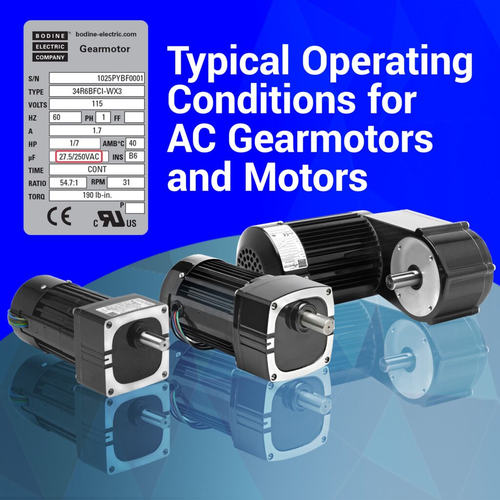
]]>The post Typical Operating Conditions for AC Gearmotors and Motors appeared first on Bodine - Gearmotor Blog.
]]>With this new Tech Note from our engineering team, you’ll learn how operating a gearmotor or motor above or below the ratings shown on its product nameplate can affect performance. For standard gearmotors, the torque rating shown on the product nameplate (or in the manufacturer’s sales literature) represents a complete gearmotor rating and reflects the capacity of the limiting gearmotor design elements. Some of the design limitations considered are: motor input power, strength or wear rating of the gearing. Click here for the full article.
Copyright Bodine Electric Company © 06/2022. All rights reserved.
The post Typical Operating Conditions for AC Gearmotors and Motors appeared first on Bodine - Gearmotor Blog.
]]>The post Introduction to Motor Constants for Fractional Horsepower Gearmotors appeared first on Bodine - Gearmotor Blog.
]]>
Common Motor Constants:
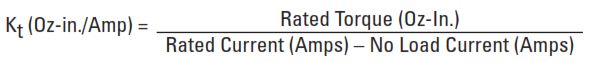
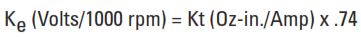
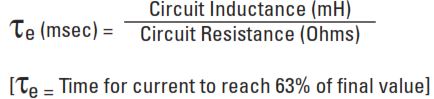
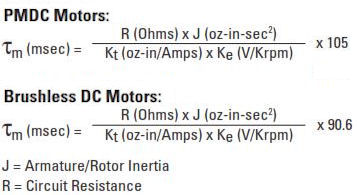
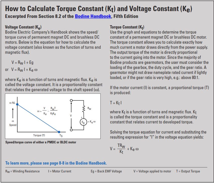
The most commonly used motor constants are Torque Constant (Kt), Voltage Constant (Ke), Electrical Time Constant (Te), Mechanical Time Constant (Tm), and Thermal Resistance (Rth). Typical values for these constants are derived by using measured values of No Load Speed, No Load Current, Stall Torque, Circuit Resistance, Circuit Inductance, and Armature Inertia with the following equations:
Torque Constant (Kt) — describes the proportional relationship between torque and current. Kt is usually expressed in the units Oz-in./Amp. See page 2 for additional information about torque constants.
Voltage Constant, or Back EMF Constant (Ke) — is the Torque Constant expressed in different units, usually Volts/Krpm, in order to describe the proportional relationship between motor speed and generated output voltage when the motor is back driven as a generator in units of Volts/1000 rpm. See page 2 for additional information about voltage constants.
Electrical Time Constant (Te) — is the time required for a motor to reach 63.2% of its stall current after applying a test voltage with the motor shaft locked. It is usually expressed in milliseconds. Applied Voltage equals Rated Current multiplied by Circuit Resistance:
Mechanical Time Constant (Tm) — is the time required for an unloaded motor to reach 63.2% of its no load speed after applying its rated voltage. It is usually expressed in milliseconds.
Thermal Resistance (Rth) — is useful for predicting the ultimate temperature rise under different loading conditions in order to determine a maximum continuous torque rating. It is usually expressed in the units °C/Watt.
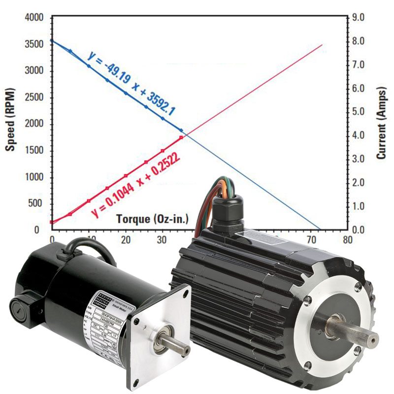
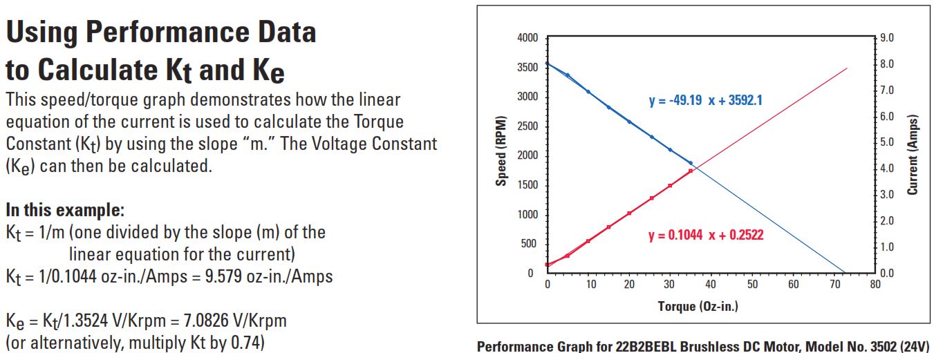
Using Performance Data to Calculate Kt and Ke
This speed/torque graph demonstrates how the linear equation of the current is used to calculate the Torque Constant (Kt) by using the slope “m.” The Voltage Constant (Ke) can then be calculated.
Using Performance Data to Calculate Kt and Ke
This speed/torque graph demonstrates how the linear equation of the current is used to calculate the Torque Constant (Kt) by using the slope “m.” The Voltage Constant (Ke) can then be calculated.
To download this information as a PDF, click here.
To download the Motor Constants for Standard Bodine Gearmotors, click here.
To download Chapter 8, or any other section of the Bodine Small Motors Handbook, click here.
Bonus Tech Tip: Another handy use for motor constants is when performing load measurements. If you are designing a machine and want to use an AC gearmotor, but you don’t know what size gearmotor you need. AC motors don’t have torque constants, but DC motors do. You might install a DC gearmotor into your prototype machine and use it as a “torque transducer”. By measuring the current draw, you can estimate what torque is needed when you start shopping for the AC gearmotor on Bodine Electric Company’s website
Copyright Bodine Electric Company © 11/2021. All rights reserved.
The post Introduction to Motor Constants for Fractional Horsepower Gearmotors appeared first on Bodine - Gearmotor Blog.
]]>The post Brush Replacement for a Bodine type 24A permanent magnet DC (PMDC) stock gearmotor or motor appeared first on Bodine - Gearmotor Blog.
]]>To watch, click here.
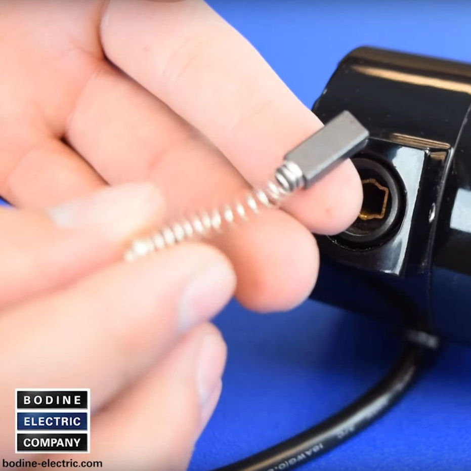
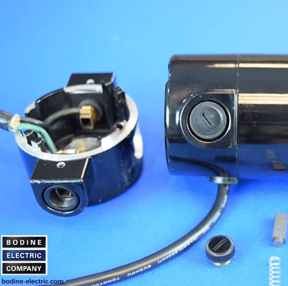
To download these instructions as a PDF, please visit our Literature page: https://www.bodine-electric.com/literature/brush-maintenance/
Copyright Bodine Electric Company © 07/2021. All rights reserved.
The post Brush Replacement for a Bodine type 24A permanent magnet DC (PMDC) stock gearmotor or motor appeared first on Bodine - Gearmotor Blog.
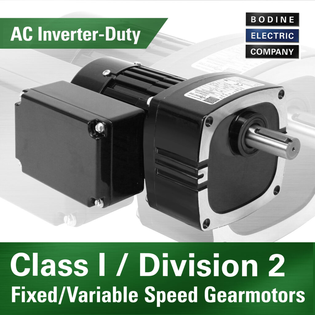
]]>The post New Fan Shrouds for Bodine type 34R, 42R, and 48R – TEFC AC Gearmotors and Motors appeared first on Bodine - Gearmotor Blog.
]]>
There are two common motor construction types of small, fractional horsepower (FHP), industrial gearmotors and motors that are available from Bodine:
TEFC – Totally Enclosed Fan Cooled (fan driven by the rotor shaft) and TENV – Totally Enclosed Non Ventilated [no external cooling fan].
Most AC induction gearmotors and motors are fan cooled (TEFC) which allows them to produce more output power. In contrast, most PMDC and Brushless DC (EC) gearmotors or motors are of TENV construction, eliminating the need for cooling fins, cooling fans, and providing much greater application flexibility due to the smaller, shorter, and often smoother motor enclosure. For some PMDC or BLDC motor applications, adding an external cooling fan to the high speed shaft can be an option to increase output power (and torque), if the gearmotor/motor is thermally limited.

Copyright Bodine Electric Company © 04/2021. All rights reserved.
The post New Fan Shrouds for Bodine type 34R, 42R, and 48R – TEFC AC Gearmotors and Motors appeared first on Bodine - Gearmotor Blog.
]]>The post Molecular Distillation Equipment for the Cannabis Industry appeared first on Bodine - Gearmotor Blog.
]]>
A manufacturer of CBD distillation equipment required a gearmotor to precisely control the flow and speed of liquid material through their new distillation apparatus.
click here for more info
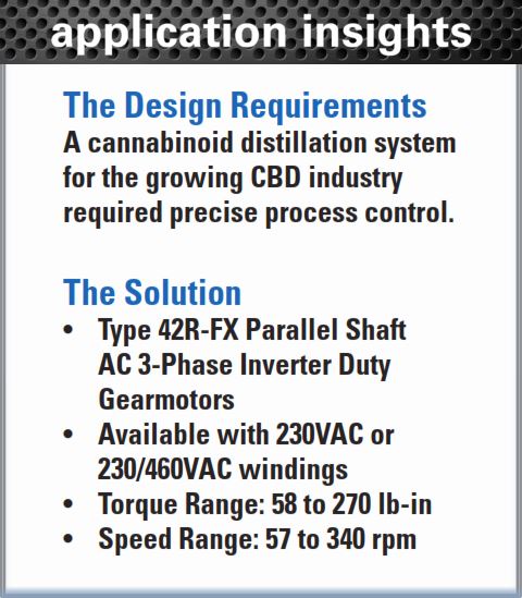
Working with an authorized Bodine distributor and our sales team, the manufacturer selected several of our variable speed AC inverter duty gearmotors, combined with inverter drives (VFDs) and a PLC control to drive the pumps and stirring mechanism within the distillation system. Earlier versions of the equipment used a competitor’s brush-type DC motor and control system. By replacing them with Bodine AC inverter-duty gearmotors, the manufacturer eliminated both brush maintenance and the noise associated with brushed DC motors.
- Standard/Stock 42R-FX AC inverter duty gearmotors
- Eliminated brush maintenance reducing machine downtime
- Lowered operational noise
Now also available from Bodine: new Class I/Div 2 AC inverter-duty and fixed speed (PSC) 34R-FX gearmotors, and CI/Div1 “Explosion-Proof” AC inverter-duty and low-voltage BLDC type 34R-FX gearmotors and 34R6BX motors.

To download this blog post as a PDF, click here.
Copyright Bodine Electric Company © 10/2020. All rights reserved.
The post Molecular Distillation Equipment for the Cannabis Industry appeared first on Bodine - Gearmotor Blog.
]]>